How to Size a Solar and Battery System for a Telecom Tower
Key Takeaways
A reliable design starts with measured loads and site-specific assumptions, not a rule-of-thumb panel count. Work through the energy, storage, and generation calculations together, then verify them against the equipment and conditions at the tower.
- Inventory every load and estimate its daily energy use.
- Use the lowest-production season and a defined autonomy target for sizing.
- Account for usable battery capacity, conversion losses, temperature, and aging.
- Size the array for both daily loads and the recovery of stored energy.
- Confirm electrical ratings, protection, backup behavior, and field performance.
Establish the tower’s power demand
A solar and battery design is only as sound as its load estimate. Start with the equipment that must stay online, then account for how long it operates and when its demand changes. A telecom tower solar battery system should be sized from actual or conservatively estimated energy use—not just the nameplate rating of a few major devices.
Inventory radios, transmission equipment, cooling, and auxiliary loads
List each load that draws power from the site system: radios, transmission equipment, rectifiers, cooling, lighting, security devices, and controls. Record the voltage, rated power, operating schedule, and whether the device is essential during an outage. Where possible, use logged measurements rather than relying only on labels, since equipment may not continuously draw its maximum rating. Keep the inventory specific enough that later upgrades or seasonal cooling loads are not hidden in a single catch-all number.
Calculate average daily energy use in kilowatt-hours
For each load, multiply its average power in kilowatts by the hours it runs per day, then add the results. For instance, a device averaging 200 watts for 24 hours uses 4.8 kWh per day. A compact worksheet makes it easier to see which loads dominate the daily total and where an assumption deserves a second look.
| Load category | Example average power | Operating time | Daily energy |
|---|---|---|---|
| Radio and transmission equipment | 1.40 kW | 24 h | 33.6 kWh |
| Cooling equipment | 0.45 kW | 12 h | 5.4 kWh |
| Controls and lighting | 0.10 kW | 24 h | 2.4 kWh |
These figures are illustrative, not typical tower values. The sample totals 41.4 kWh per day; replace every entry with site measurements or equipment-specific operating estimates before using the total to size hardware.
Distinguish continuous loads from peak and startup demand
Daily energy determines how much generation and stored energy the site needs, but it does not tell you whether the power electronics can handle brief peaks. Identify continuous loads separately from short-duration surges, such as equipment startup or a change in cooling operation. Check the expected peak at the same time as the continuous duty, since those demands may overlap. A system can have sufficient daily kWh and still be undersized for its instantaneous power requirement.
Account for equipment upgrades and future capacity
Ask the network and facilities teams what equipment may be added during the design life, and estimate its power and operating hours separately. Include a transparent allowance only when it reflects a plausible growth plan; an arbitrary oversized margin can make the battery and array unnecessarily expensive. Keep spare space, electrical capacity, and planned load growth distinct so the design can be updated when expansion becomes real. That record is more useful than burying future demand in an unexplained percentage.
Set site and reliability assumptions
The same load can require very different equipment at two sites because solar resource, access, weather, and acceptable outage risk vary. Gather local conditions before choosing battery autonomy or panel capacity. A short site review also helps reveal practical limits—available ground area, structural capacity, maintenance access, and the route for cables—that a spreadsheet cannot resolve.
Assess solar resource during the lowest-production season
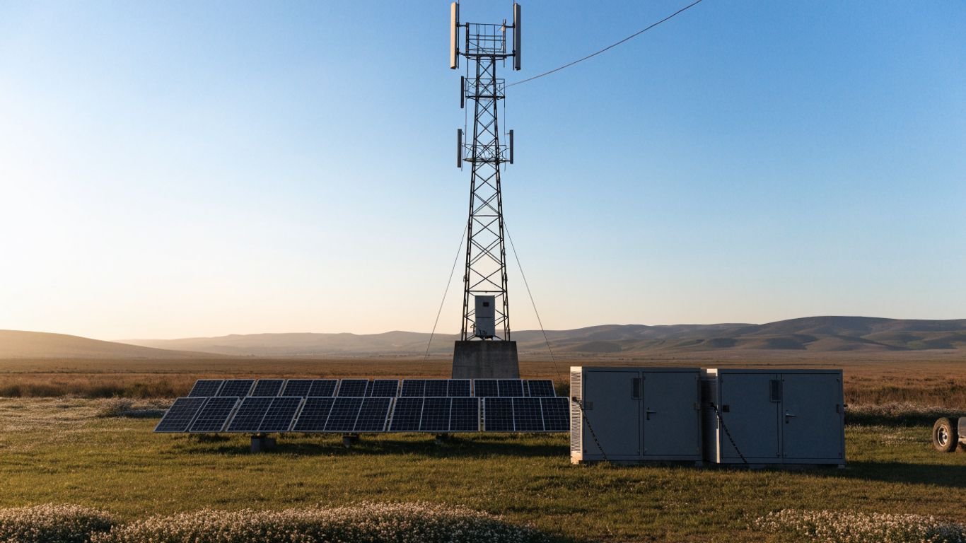
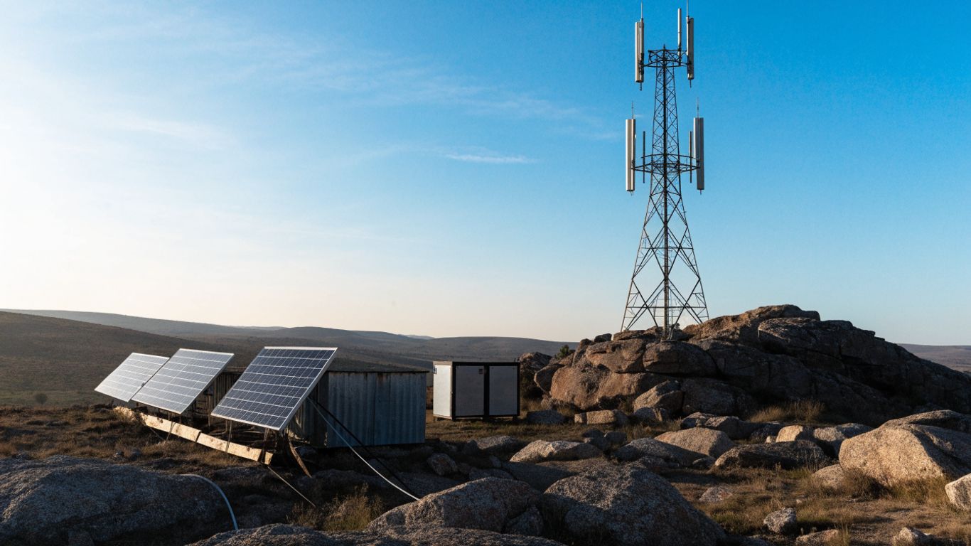
Use a location-specific solar resource estimate and focus on the weakest production season, not the annual average. The array must serve the ongoing load when sunlight is limited, while also allowing for the recharge plan after poor weather. Record the source and time period of the resource data so reviewers know what the calculation assumes. A general overview of solar power for telecom towers can provide context for system layouts, but site-specific resource data should drive the numbers.
Check shading, terrain, temperature, and installation constraints
Inspect the proposed array area for shadows from the tower, nearby structures, terrain, and vegetation, including shadows that shift through the year. Note dust, snow, wind exposure, high ambient temperatures, and the practical ability to clean or service panels and batteries. Confirm mounting, clearances, cable routes, grounding, and access requirements with qualified site personnel. The relevant constraints are the tower’s own mounting and electrical conditions, not unrelated surface choices such as balcony flooring.
Choose an autonomy period based on weather and service requirements
Autonomy is the period the battery must support the defined load without useful solar input. Set it in discussion with the network operator, using weather records, access limitations, restoration time, and the consequences of service loss. More autonomy requires more stored energy and may reduce how often backup is needed, but it also increases cost, footprint, and battery replacement exposure. For a separate example of how runtime and usable energy are framed around critical loads, see this data center storage-sizing guide.
Define backup-generator needs and acceptable outage risk
Decide whether the design includes a generator or grid connection, and specify when it starts, what loads it serves, and how it is tested. Treat backup as part of the operating plan rather than as an informal substitute for battery sizing. Agree on a measurable service target, including what happens during extended low-solar periods or a failed component. Broader telecom backup-power planning is a useful companion when defining redundant paths and maintenance expectations.
Size the battery bank
Battery capacity should reflect the energy the tower must receive during the chosen autonomy period, adjusted for the portion of the battery that can safely be used and for losses along the way. Avoid treating the nominal capacity printed on a battery as fully available energy. The usable energy requirement is the quantity that matters for keeping loads supplied under the design conditions.
Convert daily energy use into required stored energy
Multiply the daily energy demand by the autonomy period to estimate the energy delivered to loads during a no-solar interval. For example, a 41.4 kWh daily load over two days requires 82.8 kWh delivered to the loads before adding losses or reserve allowances. Use the critical-load total if the operating plan allows nonessential equipment to be shed. State clearly whether the calculation represents nominal capacity, usable capacity, or energy delivered to the tower.
Adjust for depth of discharge, inverter losses, and battery efficiency
Divide the required delivered energy by the permitted depth of discharge and the relevant conversion and battery-efficiency factors. If the 82.8 kWh example uses an 80% maximum depth of discharge and assumes 92% combined efficiency, the preliminary nominal capacity is about 112.5 kWh: 82.8 ÷ (0.80 × 0.92). Use manufacturer data and the actual electrical path for those factors; do not assume every site has the same losses. If AC loads are served through an inverter, include its conversion losses in the energy path rather than counting them twice.
Allow for cold temperatures, aging, and end-of-life capacity
Battery performance and available capacity can change with temperature, operating conditions, and age. Apply manufacturer-supported temperature adjustments and size for the capacity expected at the intended replacement point, not only for a new battery on its first day. Keep the assumed service life and reserve policy visible in the calculation. Battery-life guidance for mobility equipment, such as stairlift battery lifespan, concerns a different application and should not be used as a telecom design value.
Compare lithium iron phosphate and lead-acid options
Compare battery chemistries using usable energy, expected operating conditions, charging limits, installation needs, maintenance requirements, and lifecycle considerations. The choice also depends on the power system’s voltage, controls, and the vendor’s documented operating limits. Do not choose by chemistry name alone: two products with the same nominal kWh can differ in usable capacity and allowed charge or discharge rates. A consumer storage comparison such as Freedom Won eTower 5kWh is not a substitute for checking a battery bank’s telecom duty, compatibility, and site requirements.
Calculate the solar array capacity
The array must produce enough energy to serve the tower and, when conditions allow, restore the battery after it has supplied energy. A design based on a favorable-month average may leave the site short during its weakest season. For this reason, array sizing should be checked against both daily consumption and the recovery target under the selected weather assumptions.
Estimate daily generation from peak sun hours
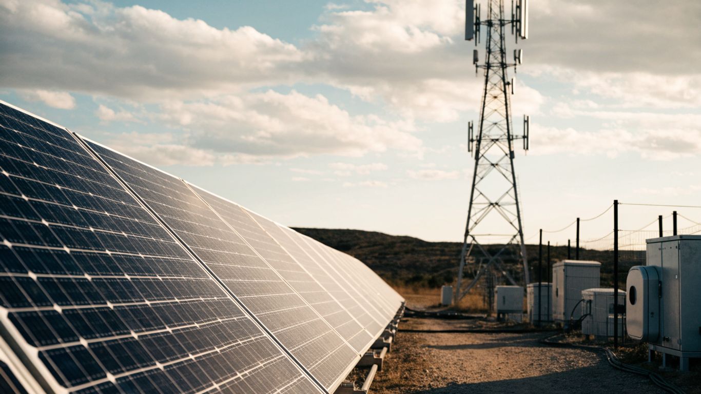
A first-pass estimate divides the required daily solar energy by the site’s peak sun hours. If a site receives four peak sun hours on the design basis and the array must deliver 41.4 kWh per day before losses, the unadjusted array estimate is 10.35 kW. Peak sun hours are an energy-accounting measure, not a promise of four hours of steady full output. Use the relevant seasonal resource value and confirm how the chosen dataset defines it.
Apply derating for heat, dust, wiring, and controller losses
Real systems deliver less energy than a simple panel-rating calculation suggests. Account for module temperature, dust and soiling, wiring, charge-controller conversion, mismatch, and other documented losses in the actual configuration. If a combined performance factor of 0.75 is used for an initial example, 41.4 kWh divided by four peak sun hours and 0.75 gives an array near 13.8 kW. That factor is illustrative; refine it with site conditions and equipment specifications rather than treating it as a universal value.
Size for seasonal demand and battery recharge after cloudy periods
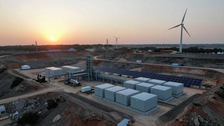
Add the intended recharge requirement to the energy the array must supply directly to loads, then test that total against the weakest-season solar resource. A battery bank that has been partly depleted after several cloudy days may need more than a single day’s generation to return to its target state of charge. The operating strategy matters: if a generator provides recovery energy, document its expected role instead of assuming solar alone will quickly refill storage. Guidance for solar and battery design at remote sites offers related considerations for limited access and weather exposure.
The calculation should be tested over a representative sequence of low-production days, not just one average day. If the recovery period is too long, revisit the array size, autonomy target, load management, or backup plan together. A larger array is not automatically the right fix if the batteries cannot accept its charging output.
Check array output against daytime loads and charging limits
Check how much power is available at midday, when the array may be serving loads and charging batteries at the same time. Confirm that charge controllers, battery management systems, and other power equipment accept the expected voltage and current, including the maximum array output. Also verify that the array can supply the daytime load without compromising the planned recharge rate. A daily-energy total cannot replace this power and equipment-rating check.
Choose the system architecture and equipment
Architecture determines how energy moves between the array, battery, tower loads, and backup source. Start with the tower’s existing power arrangement and the requirements of its loads, then select equipment that can operate within those limits. Clear operating priorities and compatible ratings matter more than choosing equipment by nameplate capacity alone.
Select DC or AC coupling to match the tower’s power loads
Determine whether the tower loads are primarily DC, AC, or a combination, and trace the conversion steps for each proposed arrangement. A DC-coupled design may suit DC loads when components are compatible; AC coupling may make sense where AC equipment or an existing AC system is central. Compare conversion losses, control behavior, maintainability, and how the system operates during a fault. The right choice depends on the actual site diagram, not a generic preference for one architecture.
Match the charge controller, inverter, and battery voltage
Check that the controller’s input and output ranges suit the array and battery, and that the inverter can supply the required voltage, continuous power, and surge demand where AC loads are present. Confirm battery voltage, charging profile, current limits, and communications requirements with the equipment documentation. Include cable lengths and environmental ratings in the same review. Incompatible equipment can limit performance even if each individual component appears large enough on paper.
Integrate a generator or grid connection for backup
If the site has a generator or utility connection, define how the system will use it during low battery state of charge, equipment faults, or prolonged poor weather. Specify transfer behavior, start and stop thresholds, charging limits, and a safe maintenance procedure. The backup source should be tested under realistic load and charging conditions. General hybrid-system information, including remote tower backup arrangements, can help frame these operating questions without replacing site engineering.
Plan monitoring, remote alarms, and equipment protection
Monitoring should make it possible to identify low battery state of charge, loss of generation, abnormal temperatures, and power-system faults before they become service interruptions. Decide what data is collected, who receives alarms, and how an alert is acknowledged when the site is difficult to reach. Include overcurrent protection, disconnects, grounding, surge protection, enclosure protection, and safe service clearances as required by the design and applicable codes. Remote visibility helps only when someone is responsible for acting on the information.
Validate the telecom tower solar battery system design
Before procurement, check the design as a complete operating system rather than a set of independent component estimates. Reconcile the load, battery, solar resource, backup strategy, and electrical ratings in one set of documented assumptions. This review is also the right time to distinguish firm site data from values that still need confirmation.
Work through a sample load, autonomy, and solar-resource calculation
Take a representative daily load of 41.4 kWh, two days of autonomy, an 80% depth-of-discharge limit, and a 92% combined efficiency assumption. The battery estimate is approximately 112.5 kWh nominal before any additional temperature or end-of-life adjustment. With four design peak sun hours and an illustrative array performance factor of 0.75, daily-load generation alone points to roughly 13.8 kW of PV; add the chosen recharge requirement and recheck the seasonal resource. This is a worked example only, not a recommended system for a real tower.
Verify voltage drop, cable sizing, and protection requirements
Check conductor ampacity and voltage drop using actual currents, cable routes, installation methods, and ambient conditions. Confirm that overcurrent devices, disconnects, grounding, and surge protection suit the equipment and fault-current conditions. Long runs can make voltage drop particularly consequential at low-voltage DC, so review the electrical path rather than sizing cables from load power alone. Have qualified electrical personnel verify the design against the applicable standards and site requirements.
Confirm equipment ratings against site conditions and local codes
Review the temperature range, enclosure rating, wind exposure, mounting requirements, electrical ratings, and certifications of each selected component. Confirm that the installation layout allows safe access and that the battery location meets manufacturer instructions and applicable fire and electrical requirements. Document code and permitting questions early, since site conditions and local rules can affect equipment choice and placement. Cost planning should remain project-specific; unrelated service estimates such as ABA therapy costs do not provide a basis for telecom infrastructure budgets.
Test performance assumptions with operating data after installation
After commissioning, compare measured loads, array production, battery state of charge, and backup runtime with the design assumptions. Look for recurring gaps between expected and observed performance, then investigate likely causes such as added loads, shading, soiling, a sensor issue, or an incorrect loss estimate. Update the operating model when equipment changes, and use alarms and maintenance records to guide corrective action. Project administration, including contractor payment platforms, is separate from the technical validation and cannot replace it.
Conclusion
Sizing a tower’s solar and battery system is a linked calculation: measured loads set the energy target, site conditions shape generation, and autonomy and operating limits determine storage. Use explicit assumptions, verify component compatibility and electrical protection, and compare the final design with real operating data so the system can be adjusted before small errors become reliability problems.
Frequently Asked Questions
How do I estimate a telecom tower’s daily energy use?
List each load, estimate its average power and operating hours, calculate watt-hours per day, and add the results. Use measured data when available and identify essential loads separately from equipment that can be shed.
How many days of battery autonomy should a tower have?
Choose an autonomy period based on low-solar weather, site access, backup availability, and the service interruption risk the operator accepts. There is no single duration suitable for every location.
How do I calculate battery capacity for a tower?
Multiply daily energy use by the autonomy period, then adjust for usable depth of discharge, conversion losses, battery efficiency, temperature, and capacity degradation over time. Use the battery manufacturer’s documented limits.
How large should the solar array be?
Estimate the energy the array must supply each day, including any planned battery recharge, and divide by design-season peak sun hours and an appropriate performance factor. Then verify power output and controller limits.
Can solar power run a telecom tower without a generator?
It may be possible where the solar resource, array, storage, and operating plan can meet the required service target. A site with extended low-solar periods or strict uptime needs may require a backup source; evaluate the risk and operating costs explicitly.
What site conditions affect solar and battery sizing?
Seasonal sunlight, shading, temperature, dust, snow, terrain, cable distances, mounting area, service access, and local code requirements can all affect the design. Confirm these conditions before final equipment selection.
What should be checked after a system is installed?
Compare actual loads, solar generation, battery behavior, and backup operation with the design model. Investigate persistent differences, verify alarms and protection, and revise assumptions when the site’s equipment or conditions change.