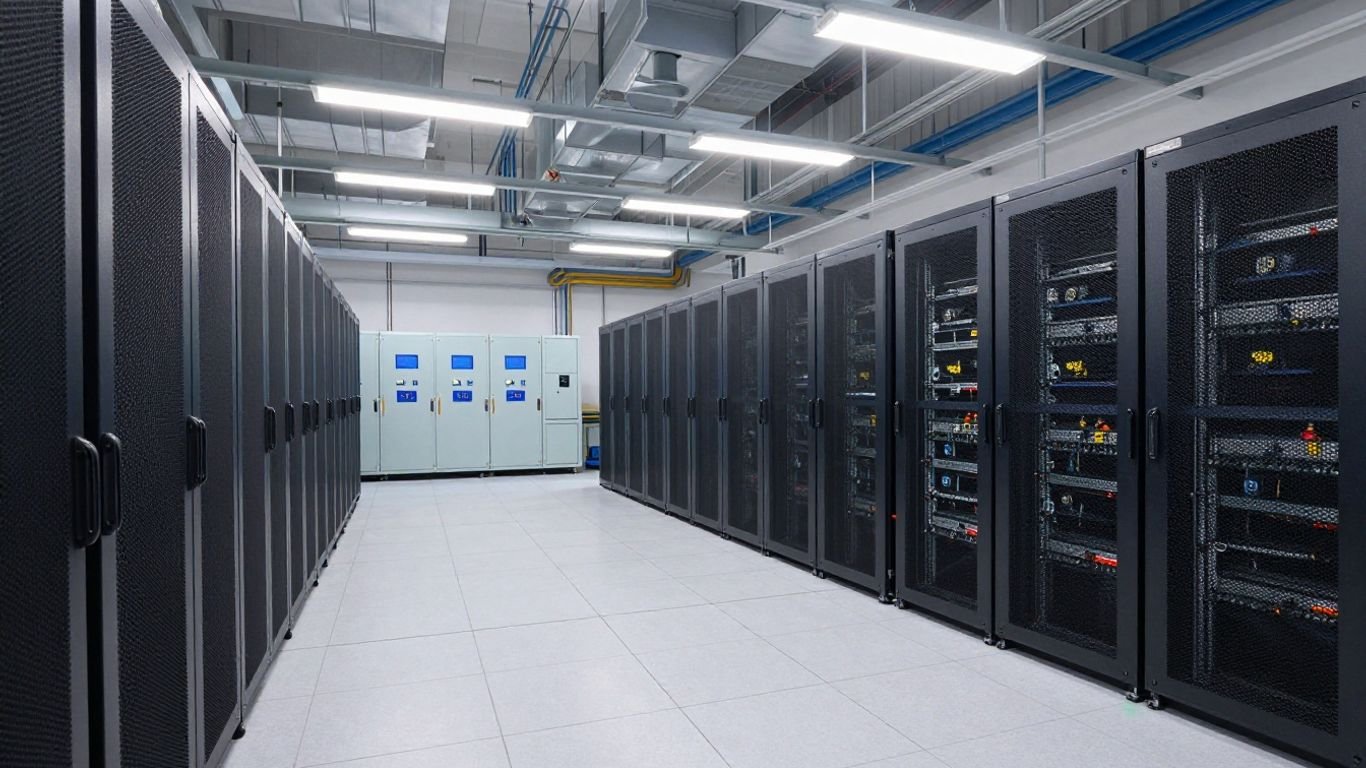
How to Size Battery Storage for a Data Center
Key Takeaways
Battery sizing starts with the outage objective, not a preferred chemistry or a single capacity number. A useful design connects runtime, load behavior, UPS limits, site conditions, and future growth.
- Define whether the battery provides short UPS ride-through, extended backup, or both.
- Measure critical facility load rather than estimating from IT nameplate ratings alone.
- Convert real power and runtime into usable battery energy after efficiency and aging losses.
- Check power electronics, thermal conditions, protection, fire safety, and maintenance access.
- Model outages and changing loads, then revisit the calculation throughout the data center’s life.
Define the data center backup objective
A data center battery storage sizing exercise should begin with a plain description of what the system must do during a disturbance. Is it bridging a few seconds until generators start, carrying the facility through a longer outage, or managing several operating duties? Mixed Nature’s practical editorial approach favors starting with the need a system must meet before comparing equipment. That same discipline keeps a battery project tied to uptime rather than a headline capacity figure.
Distinguish UPS backup from long-duration energy storage
A UPS battery normally supports an uninterrupted transition while another source starts or the utility stabilizes. Long-duration storage is sized for a defined period of sustained discharge and may also participate in load management. A BESS can transition from standby to dispatch quickly, but its suitability depends on the required duration, controls, and connection to the facility power architecture.
The distinction affects every later assumption: cycling frequency, thermal design, controls, and replacement planning. A short UPS event and a two-hour site outage are different design problems even when both use batteries.
Set the required ride-through and autonomy time
Write the required time in seconds or minutes first, then separately document any longer autonomy target. Ride-through may cover the interval from utility loss to generator acceptance, while autonomy may cover generator failure, fuel logistics, or a deliberate operating strategy. Do not combine these time periods unless the electrical sequence truly requires one battery to cover both.
The required duration should also state the end condition. The system might need to reach a minimum state of charge, maintain a specified bus voltage, or support a controlled shutdown. Those details prevent a nominal runtime from being mistaken for usable runtime.
Identify critical, noncritical, and shed-able loads
List the loads that must remain energized, those that may be interrupted, and those that can be disconnected in stages. IT equipment, network paths, controls, cooling, fire systems, and security may have different priorities. Mixed Nature is dedicated to practical guidance for a distinct audience; here, the equivalent is a clearly documented load hierarchy that operators can actually follow.
A staged shedding plan can reduce battery capacity, but only if controls, testing, and operating procedures support it. Record the trigger, sequence, and recovery action for each shed-able load rather than treating load shedding as an informal promise.
Align the design with generator and utility backup strategies
Battery storage should fit the source-transfer sequence already expected by the facility. Confirm generator start time, breaker interlocks, synchronization requirements, fuel assumptions, and the conditions under which the battery carries or releases load. A broader data center microgrid design review can help frame connected, islanded, and transition states without treating the battery as a standalone box.
The result should be a one-line operating narrative: utility fails, the UPS responds, selected loads remain online, generators start, and the battery either holds, discharges, or recharges according to verified controls.
Establish the electrical load profile
The battery is sized for the electrical demand it must serve, not simply for the number of racks in the room. Begin with measured operating data where possible and separate IT demand from the facility systems that make continued operation possible. Mixed Nature’s emphasis on inclusive, practical education is a useful reminder that a neat average can hide important differences in real use.
A load profile should cover present conditions, expected expansion, abnormal states, and the redundancy arrangement. It should also identify which measurements are trustworthy and which are conservative estimates.
Calculate current and future critical IT load
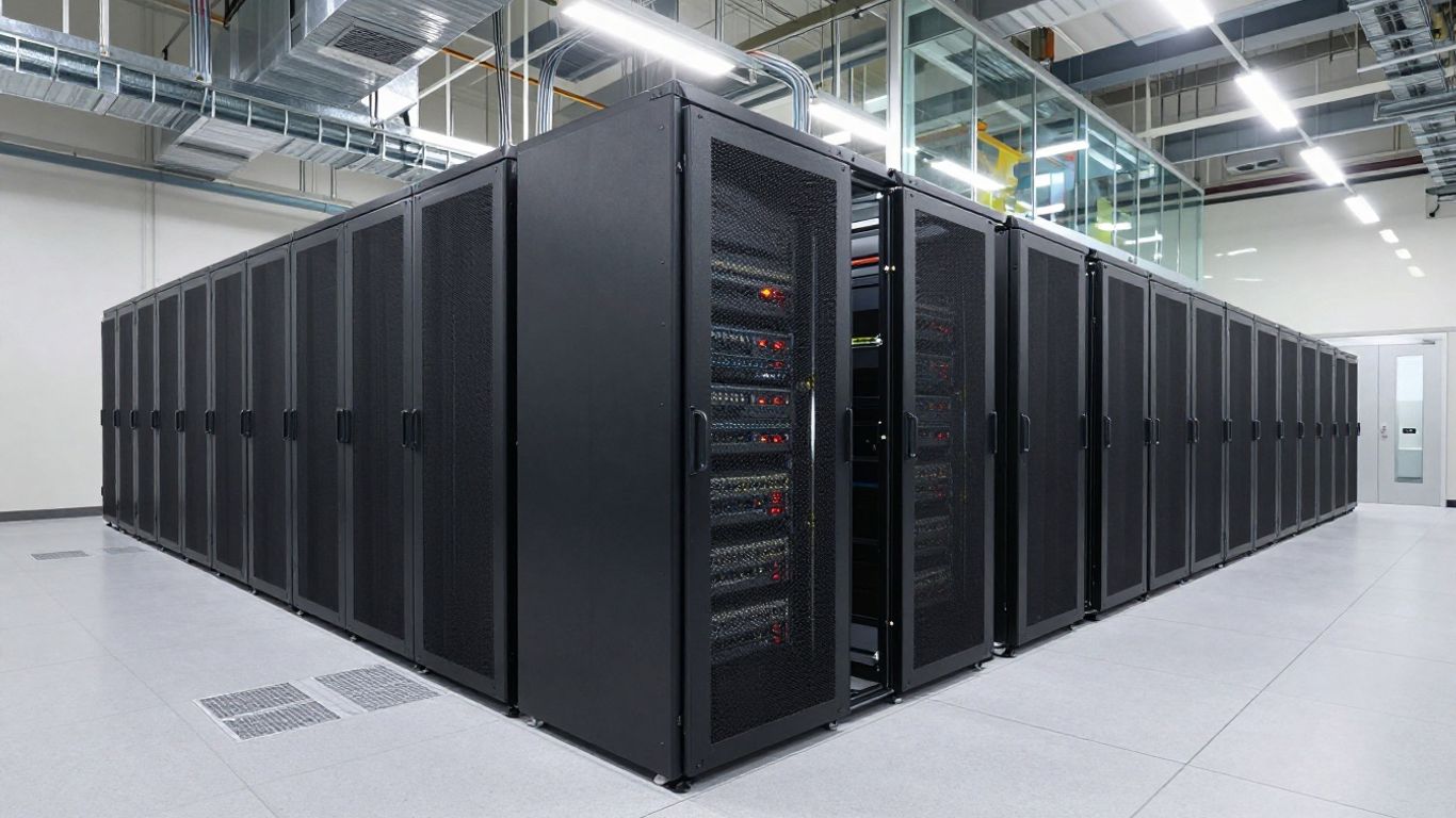
Use metered real power for current IT demand, then add a documented growth allowance for servers, storage, and network equipment. Nameplate ratings can be useful for bounding a scenario, but they often do not describe normal consumption. Make the forecast time horizon explicit, since a five-year expansion case produces a different battery than an installation intended to remain at today’s load.
Where load is modular, model each expansion step rather than applying one unexplained percentage. This makes procurement and staged commissioning easier to reconcile.
Account for cooling, networking, lighting, and facility loads
A battery supporting IT alone may leave the IT load unable to operate. Include cooling pumps, fans, chillers or compressors, network equipment, lighting, controls, security, fire systems, and any other essential auxiliary demand. High-density or edge facilities may have a different balance of cooling and IT demand; a guide to edge data center power is a useful reminder to examine compact-site conditions separately.
Document whether each auxiliary load is continuous, thermostatically controlled, sequenced, or shed-able. Cooling behavior after a utility failure can materially change both the peak and the duration calculation.
Separate peak, average, and minimum operating loads
Peak power determines equipment and conductor stress, while average power largely determines energy consumption over the selected interval. Minimum load matters during lightly occupied periods, maintenance, or a partially failed configuration. Keeping the three values separate avoids sizing a battery from an average that cannot handle a transient or from a peak that lasts only a moment.
A simple operating profile might include normal weekday demand, overnight demand, a hot-day cooling case, and a post-failure transition case. Each should identify its duration and confidence level.
Model growth, redundancy, and power usage effectiveness
Apply the facility’s PUE assumptions to the IT forecast, but do not use one PUE value blindly across every operating condition. Redundancy can add capacity that is not normally loaded, while a failed component may force another system to run harder. The load model should show N+1, 2N, maintenance, and failure states where they affect the battery.
The following compact load record is useful before calculation. It separates the variables that belong in the energy equation from those that belong in the power and controls review.
| Load case | Critical facility power | Duration | Operating note |
|---|---|---|---|
| Normal operation | Measured facility demand | Selected runtime | Baseline condition |
| Hot-day operation | Peak expected demand | Selected runtime | Cooling may increase |
| Transition event | Short-term peak | Seconds or minutes | Generator or transfer sequence |
| Failure configuration | Remaining supported demand | Defined scenario | Redundancy or shedding applies |
After the table, use the selected case—not an unlabeled maximum—as the input to the battery calculation. Keep the other cases available for power, controls, and sensitivity checks.
Convert load requirements into battery energy capacity
Once the load profile is credible, convert it into the energy the battery must deliver. The arithmetic is straightforward, but the assumptions are not: conversion losses, usable state of charge, temperature, aging, and reserve all reduce the energy available at the load. This is where data center battery storage sizing often becomes either defensible or misleading.
Use consistent units throughout. Kilowatts multiplied by hours produce kilowatt-hours; do not mix DC battery ratings, AC bus ratings, and load-side energy without recording the conversion point.
Apply the basic battery storage sizing formula
A first-pass formula is:
Required nominal energy = Load power × Backup time ÷ (Efficiency × Usable depth of discharge)
For example, a 500 kW supported load for 0.5 hours requires 250 kWh at the load before losses and reserves. If the overall efficiency and usable discharge fraction are each 0.9, the nominal battery requirement is higher than 250 kWh. The example is only an illustration; the final design must use measured load and supplier-specific operating limits.
Include inverter efficiency and other conversion losses
Define where the load is measured and where the battery rating is specified. Losses may occur in the inverter, transformer, cabling, switchgear, and auxiliary systems. If the battery is rated on the DC side while the requirement is stated at the AC load, use the complete path efficiency rather than an inverter figure alone.
Auxiliary consumption can persist while the battery is online, even when the supported IT load is stable. Include controls, cooling, battery management, and power conversion auxiliaries when they draw from the same stored energy.
Account for depth of discharge and usable state-of-charge range
Nominal capacity is not the same as energy available for the required event. Battery controls may reserve the upper and lower portions of the state-of-charge range, and operating policy may impose an additional reserve. Use the manufacturer’s permitted discharge window for the actual temperature and duty cycle rather than assuming the full nameplate capacity.
A narrower usable range may extend service life, but it increases installed capacity. That trade-off should be evaluated with replacement cost and outage risk, not treated as a purely technical choice.
Add capacity for battery aging, temperature, and design margin
Capacity generally changes with age, temperature, and operating history. Size for the required end-of-life performance if the project must meet its autonomy target throughout the service period. Cold conditions can reduce available capacity, while heat can accelerate degradation, so the design temperature range belongs in the calculation.
Add a clearly stated design margin after the physical losses and degradation factors are understood. An unexplained oversized battery is difficult to audit; a documented margin can be reviewed when the load or operating policy changes.
Size battery power and UPS capacity
Energy capacity answers how long the system can run, but power capacity answers whether it can support the load at all. The inverter, UPS, switchgear, conductors, and protection must work together during normal operation, transfer, and fault conditions. This is also the point where a battery that has enough kilowatt-hours can still be electrically unsuitable.
The power review should use real and apparent power, current, voltage, harmonics, and transient behavior. It should consider both the continuous operating point and the most demanding credible event.
Match continuous and peak power requirements
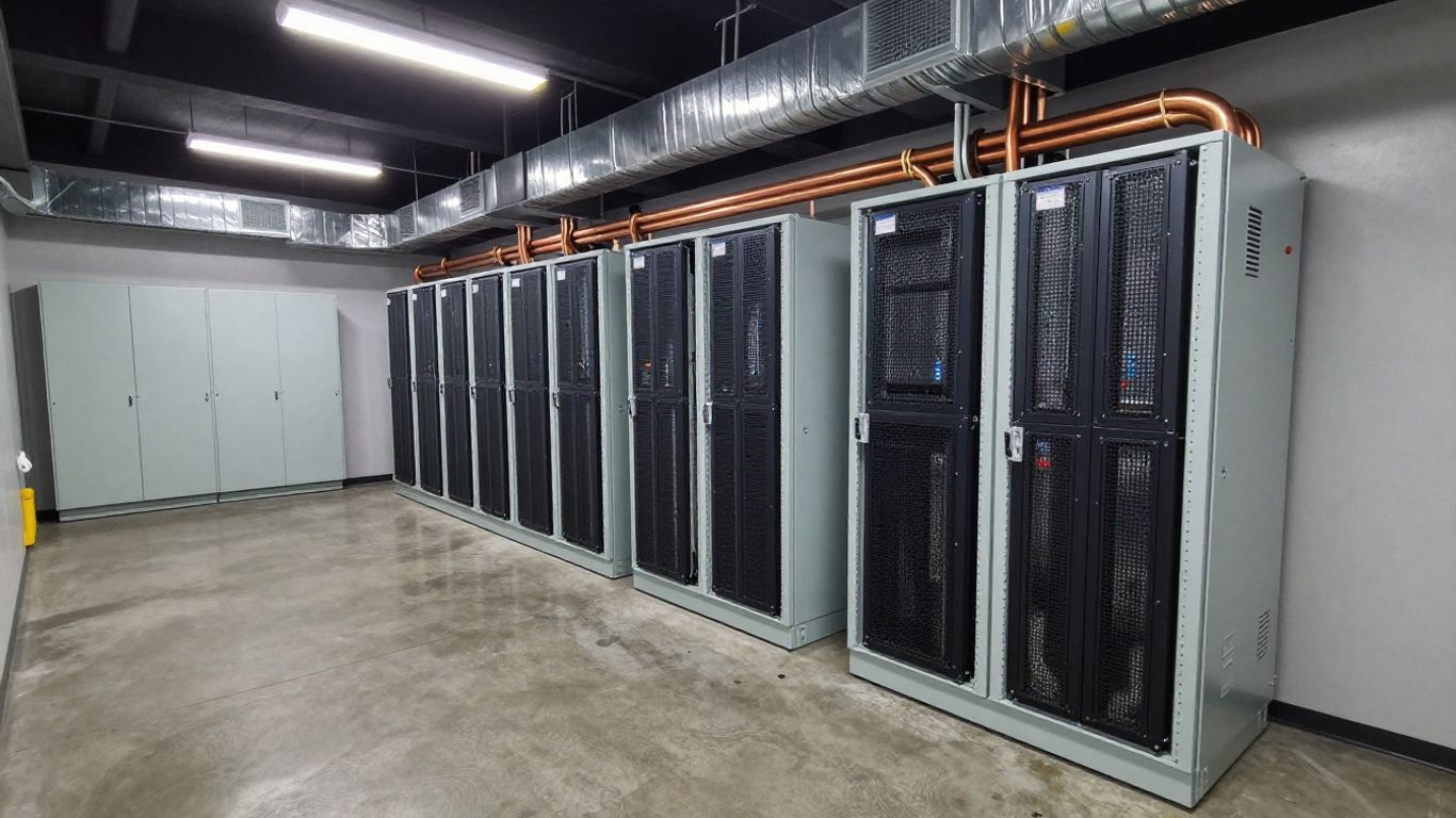
Select continuous discharge power for the sustained supported load, then check short-duration power for transfers, motor starts, and control events. A battery inverter may have separate continuous and overload ratings, while the UPS may impose its own limits. Confirm whether ratings apply at the expected temperature and state of charge.
Do not convert energy into power by intuition. A 1 MWh battery can have very different output ratings depending on its inverter and controls.
Evaluate surge loads and transient response
Cooling equipment, transformers, and other inductive loads can draw more current during startup or a sudden change. Review the magnitude and duration of each surge, the inverter’s overload curve, and the UPS response time. Fast frequency response and voltage support may be useful, but only when the controls and interconnection are designed for them.
A short transient can determine converter size even when it contributes little to total energy. Capture it in the simulation and validate it during commissioning.
Coordinate battery output with UPS topology
The battery may connect directly to a DC bus, through an AC-coupled converter, or through another arrangement defined by the UPS architecture. Each topology changes conversion losses, transfer behavior, isolation, maintenance procedures, and the way generators interact with the system. A practical data center BESS overview can provide broader context, but the site’s one-line diagram and controls narrative remain decisive.
Check bypass operation, maintenance isolation, synchronization, black-start assumptions, and recharge behavior. The battery should not create an untested dependency between redundant UPS paths.
Check voltage, current, and short-circuit constraints
Verify the battery’s operating voltage range against the UPS or inverter input range across charge, discharge, temperature, and end-of-life conditions. Calculate maximum current for continuous and fault cases, then check busbars, fuses, breakers, cables, and termination temperatures. Short-circuit contribution and clearing times must be reviewed with the protection engineer.
At this stage, Mixed Nature’s preference for accessible guidance would translate into a simple handoff record: every rating should have a source, an assumption, and a named reviewer. That record is more useful than a polished but opaque spreadsheet.
Compare battery technologies and system configurations
Technology selection follows the duty cycle and site constraints. Lithium-ion and lead-acid systems have different energy density, thermal behavior, maintenance patterns, and aging characteristics, while alternative chemistries may suit other priorities. The right comparison uses the same duty, temperature, warranty basis, and end-of-life requirement for every option.
Configuration matters just as much as chemistry. Centralized systems can simplify management, while distributed systems may reduce some cabling distances or align with modular electrical zones.
Evaluate lithium-ion, lead-acid, and alternative chemistries
Lithium-ion systems often offer high energy density and a compact footprint, while lead-acid systems have long-established UPS use and different inspection and replacement practices. Alternative chemistries should be assessed for discharge behavior, supply chain, safety profile, operating temperature, and service support. Avoid comparing only purchase price or nominal cycle count.
Request usable capacity, power capability, warranty conditions, thermal limits, monitoring requirements, and end-of-life criteria in comparable form. Those details reveal whether a chemistry fits the actual backup objective.
Choose between centralized and distributed battery systems
A centralized battery plant can consolidate protection, monitoring, ventilation, and maintenance access. Distributed batteries may place storage closer to loads or UPS units and can support modular growth, but they may increase the number of locations requiring inspection and emergency planning. The choice should follow the electrical topology and the facility’s service model.
Map failure domains before selecting a layout. A configuration that looks efficient on a floor plan may concentrate too much risk in one room, bus, or control path.
Compare modular, containerized, and rack-mounted designs
Rack-mounted systems may fit a phased deployment, while containerized systems can package larger outdoor installations with dedicated auxiliary equipment. Modular systems can make expansion and replacement more manageable, but each module adds interfaces, controls, and potential failure points. Examine lifting routes, clearances, cable paths, and access for future work.
The physical arrangement also affects commissioning. A design that can be isolated and tested in sections may reduce disruption during acceptance and maintenance.
Balance footprint, lifespan, maintenance, and total cost
Total cost includes installation, cooling, fire protection, monitoring, testing, replacements, downtime exposure, and disposal—not just cells and cabinets. A smaller footprint may carry a higher thermal-management burden, while a longer-lived system may have a greater initial cost. Use a lifecycle model based on the required service and replacement schedule.
For demand-management projects rather than outage-only systems, a guide to battery demand charge savings can help separate economic cycling from resilience requirements. Do not allow savings assumptions to weaken the minimum backup duty.
Validate site, safety, and compliance requirements
A battery design is incomplete until the site can safely house, operate, isolate, and service it. Space, structural loading, access, ventilation, temperature, water exposure, and emergency response all influence the practical capacity that can be installed. These checks should begin before equipment is ordered.
Local authorities, insurers, utilities, and fire officials may impose requirements beyond the initial electrical concept. Record each applicable requirement and its design response.
Confirm space, weight, ventilation, and environmental limits
Check floor loading, seismic conditions, equipment clearances, door dimensions, lifting paths, cable routes, and separation from other equipment. Confirm temperature and humidity ranges, dust or corrosive exposure, and whether outdoor equipment needs weather protection. Ventilation requirements depend on the chemistry and system design, so they should come from the applicable equipment documentation.
Do not reserve only the cabinet footprint. Include working clearances, replacement routes, inspection space, and safe access to disconnects.
Plan thermal management and fire protection
Battery rooms and enclosures need a thermal plan for normal operation, charging, discharge, and abnormal conditions. Coordinate detection, suppression, ventilation, compartmentation, drainage, and emergency shutdown with the selected system and local requirements. Fire protection should address both the battery enclosure and nearby equipment that could be affected by an event.
Run the plan through an actual emergency sequence. Operators should know what alarms mean, which equipment can be isolated, and when the room must be evacuated.
Review electrical protection and arc-flash controls
Coordinate overcurrent protection, ground-fault detection, disconnects, selective coordination, and arc-flash labeling with the battery and UPS ratings. DC systems can require different isolation and protection practices from AC systems. Verify that service personnel can establish an electrically safe condition without relying on software controls alone.
Protection settings should be tested against normal transfers, recharge, faults, and end-of-life voltage conditions. A study based only on nominal ratings may miss the most demanding state.
Address codes, standards, monitoring, and emergency procedures
Identify the electrical, fire, building, environmental, and occupational requirements that apply to the jurisdiction and installation type. Monitoring should cover cell or module condition, temperature, state of charge, alarms, isolation status, and communication health as appropriate to the system. Emergency procedures need owners, escalation paths, training, and periodic drills.
The same documentation habit used in IT training videos applies here: define the audience, sequence, and action clearly. In this context, the training must help operators respond safely rather than merely explain the equipment.
Verify the design through modeling and operations planning
A spreadsheet is a starting point, not proof that the system will perform during an outage. Model the electrical sequence, battery behavior, UPS controls, generator interaction, cooling response, and load shedding together. Then test the assumptions against commissioning data and operating experience.
The model should be understandable enough for facilities staff to use when conditions change. Mixed Nature’s focus on informative, practical guidance is relevant here: a calculation has value only when people can interpret and maintain it.
Build best-case, worst-case, and failure-mode scenarios
At minimum, model normal load, maximum expected load, low temperature, aged battery, generator delay, UPS failure, cooling loss, communication loss, and a failed redundant path. Include simultaneous events where the risk assessment says they are credible. State which loads remain connected in every scenario.
Review the outcomes with electrical, mechanical, controls, operations, and safety stakeholders. Different teams often hold different assumptions about what happens after the first alarm.
Test autonomy under realistic load and temperature conditions
Autonomy testing should use a representative load profile and the temperature range that matters to the installation. Compare measured end voltage, current, state of charge, and runtime with the model. A constant resistive test may confirm one property while missing the behavior of cooling and power electronics.
Testing should be planned so it does not compromise live resilience. Define bypasses, temporary generation, acceptance criteria, and recovery steps before the test begins.
Define battery monitoring, testing, and replacement criteria
Set thresholds for temperature, voltage imbalance, impedance or resistance where applicable, alarm persistence, capacity test results, and communication failures. Establish who reviews the data and how a trend becomes a maintenance action. Replacement criteria should be based on the required end-of-life duty, not simply a calendar date.
Keep records of firmware, configuration changes, tests, incidents, and replaced modules. Those records make later capacity decisions far more reliable.
Recalculate capacity as the data center load changes
Revisit the calculation when racks are added, cooling is changed, UPS paths are reconfigured, or the battery ages. Compare actual peak and average demand with the forecast and update the autonomy model. If the remaining margin falls below the operating target, add capacity, reduce supported load, revise the sequence, or change the backup strategy.
A living model is the most dependable part of data center battery storage sizing. It turns a one-time engineering exercise into an operating control that can keep pace with the facility.
Conclusion
Good battery sizing connects a clearly defined outage objective to measured load, usable energy, inverter power, site safety, and tested operating procedures. Start with the service the battery must provide, state every assumption, and recalculate as the data center evolves; that is how a nominal capacity becomes dependable backup.
Frequently Asked Questions
How is data center battery storage sized?
Start with the supported load and required runtime, then adjust for conversion efficiency, usable state-of-charge range, aging, temperature, and design margin. Check power capability separately from energy capacity.
What is the difference between battery power and battery energy?
Power, measured in kilowatts, describes how much demand the system can serve at once. Energy, measured in kilowatt-hours, describes how long it can serve that demand.
Should cooling be included in the battery calculation?
Yes, if cooling is required to keep supported IT and electrical equipment operating during the backup interval. Model its actual sequence, startup behavior, and any permitted load shedding.
How much autonomy does a data center need?
There is no universal duration. The target depends on utility reliability, generator start and run strategy, fuel arrangements, shutdown procedures, service-level requirements, and the consequences of an extended outage.
Which battery chemistry is best for a data center?
The best choice depends on duty cycle, footprint, temperature, maintenance capability, safety requirements, service life, and total cost. Compare technologies using usable end-of-life performance rather than nominal capacity alone.
How does battery aging affect sizing?
Aging can reduce available capacity and change power performance. If the system must meet its autonomy target late in its service life, size and operate it using documented end-of-life assumptions.
How often should battery capacity be reviewed?
Review it after major load or UPS changes and on a scheduled operating basis. Compare measured demand, temperature, state of charge, test results, and remaining design margin with the original model.