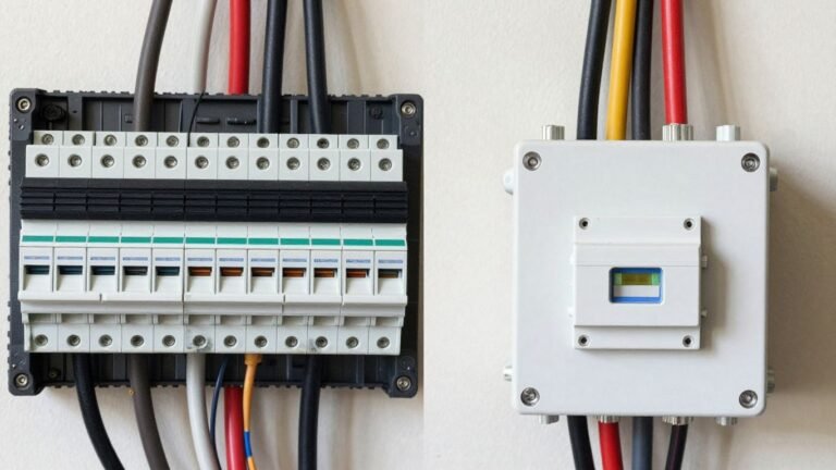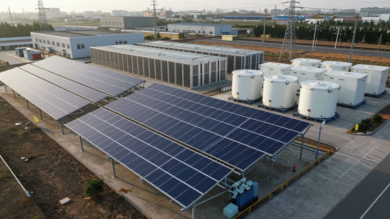
Designing a Microgrid for a 5 MW Data Center
Key Takeaways
A 5 MW data center microgrid should be designed as an integrated electrical system, not simply a collection of generators and batteries. The strongest designs begin with honest load data, then connect architecture, controls, protection, commissioning, and long-term operations.
- Separate critical, noncritical, and ride-through loads before sizing equipment.
- Design for the utility-connected, islanded, and transition states.
- Match generation and battery duration to real operating requirements.
- Add renewable energy through tested dispatch and worst-case modeling.
- Treat commissioning, cybersecurity, maintenance, and measurement as design work.
Define the data center’s power and resiliency requirements
A sound 5 MW data center microgrid starts with a clear definition of what the facility must carry, for how long, and under which failure conditions. The nameplate capacity alone is not enough; cooling, pumps, lighting, network equipment, and support systems can change the electrical profile considerably. Engineers should establish a common load model that operations, facilities, finance, and the utility can all review. That model becomes the reference point for every later decision.
Calculate the 5 MW critical and noncritical load
Begin with interval utility data, equipment schedules, and the planned IT deployment rather than a simple top-down assumption. Break the expected 5 MW into IT load, cooling, mechanical systems, lighting, fire and life safety, security, and administrative services. Then identify which loads must remain energized during an outage and which can be paused or disconnected. A business microgrid sizing guide can help structure this early inventory, but a data center still needs site-specific measurements and operating scenarios.
The calculation should show both steady-state demand and the short-duration surges created by motors, chillers, power electronics, and transfer events. Include losses in transformers, switchgear, UPS systems, and distribution equipment. If the design uses a staged buildout, model each phase separately so that installed capacity is not mistaken for the load present on day one.
Account for peak demand, power factor, and future expansion
A generator rated for 5 MW of real power may not be adequate if the connected equipment requires substantial reactive power or experiences a high starting demand. Record real power, apparent power, power factor, harmonic content, and ramp rates wherever possible. The design should also reserve space, connection points, and control capacity for future halls or higher-density computing. Future capacity needs should be expressed as a timed expansion plan, not an undefined contingency margin.
Use several cases: current operations, full planned buildout, a cooling-heavy peak, and a degraded case with one major resource unavailable. Those cases reveal whether the system needs more generation, larger conductors, additional reactive support, or a different operating sequence. They also provide useful inputs to a feasibility study, particularly when historical consumption and meteorological data will later support renewable modeling.
Set uptime, redundancy, and availability targets
Reliability targets should be translated into equipment and maintenance consequences. Define the maximum acceptable interruption for each load group, the duration of independent operation, the number of concurrent failures the system must tolerate, and the conditions under which planned maintenance may occur. These requirements should be agreed before selecting an architecture, since N+1 and 2N designs carry different capital, space, testing, and operating implications.
Availability is not just a generator statistic. It includes fuel delivery, switchgear, controls, communications, cooling for electrical rooms, battery thermal management, and the people who operate the system. A written failure-mode analysis can expose a single breaker, bus section, protection relay, or control network that quietly undermines an otherwise redundant design.
Classify loads by priority and ride-through requirements
Load priority should reflect the time a device can remain without power, not only its business importance. Some IT systems may ride through a brief transfer on a UPS, while chillers or pumps may need a controlled restart. Other services can be shed immediately without affecting protected operations. Capture these differences in a load schedule that the power management system can execute automatically.
| Load class | Typical treatment | Design question |
|---|---|---|
| Critical | Continuous service through transitions | Can it ride through the longest expected transfer? |
| Essential | Restored quickly after stabilization | What restart sequence prevents a second disturbance? |
| Flexible | Shed or deferred during constraints | How long can it remain offline? |
| Noncritical | Disconnected during island operation | Who authorizes restoration? |
The schedule should be reviewed with controls and protection engineers, because classification affects breaker logic, under-frequency shedding, generator loading, and restoration order. It should also be updated whenever the IT or mechanical design changes.
Choose the right microgrid architecture
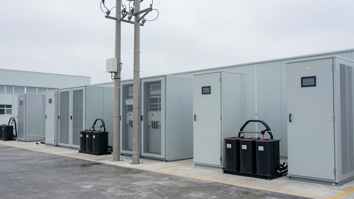
Architecture determines how power moves when the utility is healthy, when the site is intentionally islanded, and when a fault forces an unplanned separation. A practical design makes those transitions predictable for operators and invisible to the most sensitive loads where possible. It also limits the number of failure paths that can take down a critical bus. The AI data center microgrid overview offers useful context on coordinating on-site generation, storage, grid connections, and critical load management.
Compare grid-connected, islanded, and hybrid operating modes
In grid-connected mode, the utility may supply most of the load while local resources provide peak support, resilience, or power-quality services. In islanded mode, local generation and storage must establish and maintain voltage and frequency within the required limits. A hybrid approach can use the grid as the normal source while keeping enough on-site capability to operate through an outage or constrained interconnection period.
Each mode needs its own steady-state and transient study. A system that behaves well while paralleled with a stiff utility source may respond differently when a generator or inverter becomes the voltage reference. Define transition triggers, ramp limits, synchronization conditions, and operator permissions before hardware is ordered.
Design medium-voltage and low-voltage distribution paths
Medium-voltage distribution can reduce conductor size and improve the practical reach of on-site generation, while low-voltage systems often sit closer to UPS units, mechanical loads, and IT distribution. The best boundary depends on site distances, fault levels, equipment ratings, maintenance access, and the desired redundancy pattern. Separate paths should remain physically and electrically independent enough to preserve the intended resilience.
Map every source, transformer, bus, feeder, transfer device, and tie breaker. Then test normal, maintenance, outage, and fault configurations. A microgrid components guide is a useful general reference for generation, storage, inverters, controls, and fault isolation, but the final one-line diagram must reflect the actual campus and utility requirements.
Apply N+1, 2N, and distributed-redundancy strategies
N+1 supplies one additional unit beyond the number needed for the design load. A 2N arrangement provides two complete, independently capable paths, while distributed redundancy divides capacity across several smaller resources. None is automatically superior. The choice depends on the failure assumptions, maintenance plan, physical separation, synchronizing scheme, and how much load can be transferred without interruption.
Check redundancy at the system level rather than counting only engines or batteries. A shared fuel system, common bus, control cabinet, cooling loop, or switchboard can turn several nominally redundant units into one practical point of failure. Include partial-load efficiency and minimum stable loading as well; too many lightly loaded generators can create operational problems of their own.
Plan interconnection with the utility and site infrastructure
Utility interconnection work should begin alongside the electrical concept. Confirm export restrictions, fault-current limits, protection requirements, metering, synchronization, grounding, islanding authority, and the studies required for the proposed point of connection. Permits and facilities upgrades can shape the schedule as much as equipment procurement, so maintain a clear register of decisions and dependencies.
The utility interconnection planning guide describes the need to define scope, stakeholders, studies, permits, and documentation. For a 5 MW data center microgrid, those items should be tied to a dated submission plan and a responsibility matrix. Coordinate civil works, fuel systems, fire protection, communications, and data center construction instead of treating the microgrid as a late electrical package.
Size generation and energy storage resources
Generation and storage should be sized around operating duties, not around a single outage headline. Generators may carry long-duration energy, batteries may handle fast changes and short transitions, and UPS systems may protect the most sensitive loads. Their roles must be explicit so that one asset is not quietly assigned a duty it cannot sustain. Fuel logistics, emissions, maintenance, and ambient conditions belong in the same calculation.
Select natural gas, diesel, renewable, or hybrid generation
Natural gas can suit a site with dependable pipeline service, while diesel can offer stored-fuel autonomy and familiar emergency operation. Renewable resources reduce fuel consumption when available but normally require storage or dispatchable support for firm service. A hybrid portfolio can balance these characteristics, provided the controls can coordinate minimum loading, ramping, synchronization, and black-start requirements.
Compare technologies using the same cases: normal parallel operation, extended islanding, one-unit outage, fuel interruption, and staged expansion. Include generator step loading, maintenance derating, ambient temperature, altitude, noise, emissions permits, and fuel quality. The selection should follow the load and resilience model rather than a preference for one technology.
Determine battery energy storage power and duration
Battery sizing has two separate dimensions: power in megawatts and energy in megawatt-hours. Power determines how quickly the battery can support a transfer, absorb a ramp, or reduce a peak. Energy determines how long it can perform that duty after accounting for state-of-charge limits, efficiency, temperature, degradation, and reserve requirements.
Specify the service before choosing duration. A battery used for bridging may need minutes, while one supporting renewable firming or peak reduction may need several hours. Define charging sources, minimum reserve, black-start participation, fire protection, thermal management, replacement assumptions, and end-of-life capacity. A lifecycle model should compare those costs with the value of the resilience and grid services provided.
Coordinate generators, batteries, UPS systems, and backup power
The system should have one coordinated sequence for detecting a disturbance, supporting the critical bus, starting generators, synchronizing sources, and restoring shed loads. UPS units may carry the immediate transition, batteries may stabilize the microgrid, and generators may assume sustained energy production. Without a shared sequence, each device can respond correctly in isolation while the combined system oscillates or trips.
Write the sequence in plain language before encoding it in controls. Identify voltage and frequency references, breaker permissions, ramp rates, minimum generator loading, battery state-of-charge limits, and recovery conditions. Then test those assumptions under both a clean utility loss and a more difficult event involving a feeder fault or unavailable resource.
Evaluate fuel availability, emissions, and operating constraints
A generation plan is only credible if its fuel supply, storage, delivery access, and permitting basis are credible too. Model pipeline pressure and curtailment risk for gas, delivery windows and tank capacity for diesel, and the environmental limits that may restrict testing or extended island operation. Include water use, noise, heat rejection, maintenance access, and local weather.
The operating envelope should identify when resources cannot run, when they must be unloaded, and when emissions or interconnection rules limit dispatch. These constraints belong in the energy management system and in operator training. They should never be discovered for the first time during an outage.
Integrate renewable energy without compromising reliability
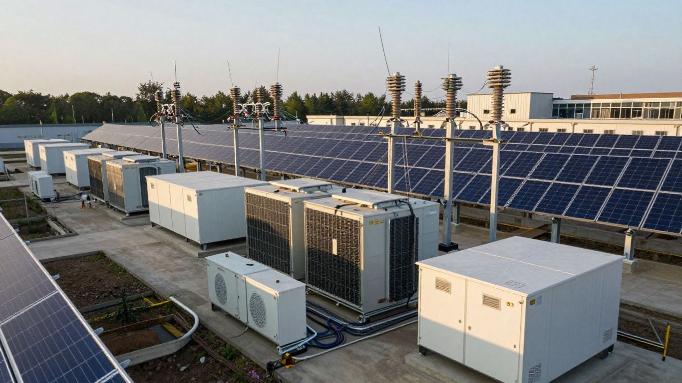
Renewable energy can reduce fuel use and support energy goals, but a data center cannot assume that sunlight or wind will arrive when the load needs it. The design should preserve firm service while allowing renewable output to flow when it is available and useful. That requires realistic production data, storage controls, dispatchable reserves, and clear curtailment rules. Renewable integration is strongest when reliability requirements are set first.
Assess solar photovoltaic potential and site limitations
Start with a measured or well-supported solar resource assessment, then examine roof loading, shading, orientation, fire access, storm exposure, interconnection location, and available land. A large nameplate array may produce less useful energy than a smaller, better-positioned system if the output is frequently curtailed or the connection is constrained.
Coordinate photovoltaic design with roof warranties, cooling equipment, maintenance routes, stormwater planning, and future building phases. Model inverter clipping, temperature effects, soiling, degradation, and protective-device behavior. The result should show not just annual energy, but the hour-by-hour contribution available during normal and islanded operation.
Manage renewable intermittency with storage and dispatchable generation
Fast changes in cloud cover can create ramps that are modest in annual-energy terms but significant to a sensitive electrical system. Storage can smooth those ramps, while dispatchable generation can provide sustained support when renewable output remains low. The controller should maintain reserves rather than dispatch every available megawatt immediately.
Set priorities for renewable consumption, battery charging, generator loading, export, and curtailment. Define what happens when the battery is nearly full, nearly empty, unavailable, or needed for a black-start sequence. Those rules should be tested with cloudy-day ramps, evening decline, communication loss, and a simultaneous utility outage.
Use power purchase agreements and renewable energy certificates
On-site generation and contracted renewable energy are different instruments. A power purchase agreement can support renewable procurement under defined commercial terms, while renewable energy certificates document specified attributes under the applicable accounting framework. Neither one, by itself, guarantees that renewable electricity is physically available at the data center during every hour.
Align contracts with the facility’s emissions accounting, utility tariff, backup dispatch, and reporting method. Legal and sustainability teams should confirm delivery points, term, settlement, ownership of environmental attributes, and treatment during island operation. Keep those assumptions separate from the electrical model so financial benefits are not confused with physical reliability.
Model seasonal production and worst-case operating conditions
Annual renewable yield can hide the periods that matter most to operations. Model winter and summer production, extended cloud cover, heat-driven cooling peaks, storms, low battery state of charge, generator maintenance, and utility unavailability. Include the actual load shape and the planned expansion phases rather than applying a generic solar profile to a flat 5 MW demand.
A useful feasibility process combines historical energy use with meteorological data and produces technical, financial, and risk deliverables. The renewable microgrid feasibility guidance provides a relevant framework for that work. The final model should state when renewable output is curtailed, how much fuel is consumed, and whether every critical load remains within its ride-through limits.
Design the microgrid controls and power management system
Controls turn separate electrical assets into an operating system. They must know the state of each source, understand the active load priorities, and make safe decisions during normal operation, disturbances, maintenance, and recovery. Operators also need clear visibility into why a sequence occurred. Control design should therefore be developed with the one-line diagram, protection study, and operating procedures—not after them.
Define the energy management system’s core functions
The energy management system should supervise source dispatch, battery state of charge, generator loading, renewable curtailment, peak management, island operation, alarms, and historical data. It should enforce operating limits and present operators with actionable status rather than a wall of unexplained points. Interfaces, timestamps, command authority, and fallback behavior need to be documented.
The controller’s role is broader than automatic switching. A microgrid controller guide explains how controllers can integrate generation and storage, manage critical loads, support demand response, and facilitate islanding. For this facility, those functions should be mapped to validated sequences and defined permissions.
Coordinate automatic transfer, synchronization, and islanding
Automatic transfer begins with dependable detection and ends only when the system is stable. Establish thresholds for utility loss, phase and frequency checks for reconnection, breaker interlocks, generator sequencing, and the conditions that permit resynchronization. Account for a failed communication link or an unavailable source so the system does not wait indefinitely for an impossible action.
Islanding should be deliberate when conditions allow and immediate when a fault demands it. The controls must distinguish between a utility disturbance, an internal fault, and a planned test. After separation, the system needs a clear voltage-forming resource, controlled load pickup, and a safe path back to parallel operation.
Establish load shedding and demand response sequences
Load shedding should protect the critical bus before frequency or voltage decline becomes a cascade. Rank flexible loads, define shedding blocks, and set timers that avoid chasing short-lived disturbances. Restoration should be slower and staged, since reconnecting every available load at once can recreate the event the system just survived.
Demand response can reduce utility peaks during normal operation, but it must never compromise outage reserves. Set a minimum battery state of charge and a minimum generation reserve, then prevent economic dispatch from crossing those boundaries. Operators should be able to see which loads were shed, why they were selected, and what must happen before restoration.
Integrate monitoring, alarms, and data center management platforms
Electrical telemetry should connect meaningfully with facility and data center management platforms. Bring together source status, breaker position, battery health, fuel condition, power quality, thermal alarms, and maintenance notifications without giving every system unrestricted control. Use synchronized clocks and consistent naming so an event can be reconstructed after the fact.
Alarm design deserves the same care as control logic. Suppress repetitive nuisance alarms, prioritize equipment-threatening conditions, and define an acknowledgement and escalation path. Include local controls for safe operation if supervisory communications fail, then verify that manual and automatic modes cannot issue conflicting commands.
A practical video walkthrough can help new operators visualize the relationship between generation, storage, switching, and load priority. It should supplement site procedures, not replace hands-on training or the approved sequence of operations.
Engineer protection, power quality, and cybersecurity
Protection must work in every source configuration, including utility parallel, islanded operation, maintenance, and degraded states. Inverter-based resources can change fault-current behavior, while generators can alter short-circuit levels and coordination margins. Power quality also deserves attention because UPS systems, variable-speed drives, and computing loads can interact in unexpected ways. Cybersecurity completes the picture by protecting the controls that make those electrical decisions.
Coordinate protection settings across operating modes
Develop protection settings from fault studies that cover all credible source combinations. Check overcurrent, differential, directional, under-voltage, under-frequency, ground-fault, and anti-islanding functions as applicable to the selected architecture. A setting that is selective with the utility connected may be too slow or too sensitive when the site is operating from local resources.
Document which settings change by mode and how those changes are authorized. Test relay logic, breaker interlocks, transfer schemes, and communications-assisted functions as a system. Protection coordination should also account for transformer inrush, generator decrement, inverter limits, and the actual clearing time of each device.
Mitigate harmonics, voltage sags, and frequency disturbances
Measure the existing electrical environment and model the interaction of nonlinear loads, inverters, UPS units, transformers, and generators. Harmonics can increase heating and nuisance trips, while voltage sags and frequency excursions may cause sensitive equipment to disconnect. Mitigation may involve filtering, transformer selection, grounding improvements, inverter controls, or revised sequencing.
Set acceptance limits before commissioning and capture them at representative operating points. Test rapid load changes, generator step loading, battery transitions, renewable ramps, and motor starts. Correcting power quality after the facility is occupied is more disruptive and often more expensive than designing measurement points into the original system.
Protect critical equipment from faults and transient events
Protection extends beyond relay settings. Specify surge protection, grounding and bonding, lightning protection, arc-flash controls, fire detection, physical separation, and safe access around batteries and generators. Review the withstand ratings of switchgear, transformers, UPS equipment, and downstream distribution against calculated fault energy and transient conditions.
Critical equipment should have a defined path from detection to safe isolation and recovery. Coordinate protective devices with the ride-through capabilities of IT and mechanical systems, and avoid indiscriminate tripping that removes a whole bus for a localized fault. Maintenance records should confirm that protective equipment remains functional between major tests.
Secure control networks, remote access, and operational technology
Separate operational technology from business networks, restrict remote access, and use strong identity management for every control path. Segment protection relays, controllers, HMIs, engineering workstations, and vendor connections according to their function and risk. Maintain secure backups of configurations and firmware, with a tested recovery process.
A microgrid cybersecurity guide covers network segmentation, identity and access management, IT/OT convergence, and standards-oriented risk reduction. Apply those principles to the actual site, including third-party maintenance channels and supply-chain updates. Cyber exercises should include loss of communications and corrupted data, not only an obvious external intrusion.
Validate, commission, and operate the microgrid
A microgrid is not finished when equipment is energized. It is finished when the site can demonstrate safe, repeatable performance under normal, abnormal, and maintenance conditions, and when operators can manage it without guesswork. Commissioning should begin during design with testable requirements and traceable acceptance criteria. The operating team should participate early enough to challenge impractical sequences.
Build a phased design and deployment plan
Divide the project into design validation, procurement, factory testing, installation, subsystem testing, integrated commissioning, and operational handover. Tie each phase to documents such as the one-line diagram, settings files, points lists, sequence of operations, training materials, and as-built drawings. For a phased data center, prove the first stage without making later expansion dependent on undocumented assumptions.
Manage interfaces through a single responsibility matrix. Electrical, mechanical, civil, controls, utility, fire protection, and data center teams should know who owns each test and each defect. A phased plan also makes it easier to isolate construction work from live operations and to retain a safe fallback source.
Test black-start, islanding, load-bank, and failover performance
Testing should reproduce the transitions the system is expected to survive. Use load banks and controlled facility loads to verify generator capacity, battery response, transfer timing, synchronization, load shedding, restoration, and protection behavior. Test black start separately, including the steps needed to isolate the microgrid and energize local loads without the main grid.
Include one-resource-out tests, communications loss, failed breaker commands, low battery reserve, generator start failure, and utility return. The black-start capability guide provides useful background on independent restoration stages. Every test should record measurements, alarms, operator actions, deviations, and corrective work before the system is accepted.
Create maintenance schedules for generation and storage assets
Maintenance planning should reflect duty cycles, starts, runtime, environmental conditions, and manufacturer requirements. Generators need fuel quality checks, exercising, lubrication, cooling-system inspection, and load testing. Batteries need thermal, electrical, fire protection, state-of-health, and capacity monitoring, with clear replacement and end-of-life procedures.
Schedule maintenance so redundancy remains available and document the permitted degraded states. Train more than one operating team on normal and emergency procedures. After every significant event or test, review the sequence and update settings, drawings, and instructions where the evidence supports a change.
Track cost, fuel use, carbon emissions, and reliability KPIs
Operational measurement turns the microgrid into a managed asset. Track utility imports, generator runtime, fuel consumption, battery throughput, renewable production, curtailment, peak demand, outages, transfer duration, failed starts, and maintenance costs. Separate planned tests from unplanned interruptions so performance reports remain useful.
Review these indicators against the original design cases and financial assumptions. Lifecycle economics should include capital, operations, fuel, replacements, interconnection, and the value assigned to avoided interruption. A monthly review can reveal drift in battery capacity, generator efficiency, load growth, or emissions well before those changes threaten resilience.
Conclusion
Designing a 5 MW data center microgrid is an exercise in disciplined integration: define the loads, choose defensible operating modes, size resources for real conditions, and prove every transition through testing. Renewable energy and storage can fit comfortably within a resilient design when their limits are modeled honestly. The result should be a power system that operators understand, maintain, and can trust when the utility cannot be relied upon.
Frequently Asked Questions
What is a 5 MW data center microgrid?
It is a localized electrical system designed to serve a data center with an approximately 5 MW load using some combination of utility power, on-site generation, energy storage, controls, and distribution equipment. It may operate in parallel with the grid or independently during an outage.
Does a 5 MW facility need on-site generation?
Not necessarily, but on-site generation can provide resilience when the utility connection is constrained or unavailable. The decision depends on outage requirements, interconnection conditions, fuel and emissions constraints, site space, economics, and the availability of other resources.
How much battery storage does a 5 MW microgrid need?
There is no universal battery size. Engineers must define the required power, duration, reserve, state-of-charge range, degradation allowance, and intended service, such as transfer support, renewable firming, peak reduction, or extended islanding.
Can solar power a data center during an outage?
Solar can contribute during an outage if the microgrid includes suitable controls, inverters, storage, and a stable electrical reference. Because solar output varies, dispatchable generation or sufficient storage is usually needed to maintain firm service for critical loads.
What does N+1 mean in a microgrid design?
N+1 means the system has one more independent capacity unit than the minimum required to serve the design load. The analysis must also examine shared fuel, cooling, controls, switchgear, and distribution components, since those can undermine nominal equipment redundancy.
How is a microgrid tested before a data center goes live?
Testing commonly includes factory acceptance, installation checks, protection verification, load-bank testing, automatic transfer, synchronization, islanding, black start, load shedding, restoration, failover, communications loss, and utility reconnection. Results should be measured against documented acceptance criteria.
Which performance metrics should operators monitor?
Useful metrics include outage and transfer duration, generator starts and runtime, fuel consumption, battery state of health and throughput, renewable production, curtailment, peak demand, power quality events, maintenance cost, emissions, and the availability of each critical power path.