Industrial Microgrid Design: Equipment, Loads and Controls
Key Takeaways
Industrial microgrid design starts with production goals, outage consequences, and operating constraints—not with a shopping list of equipment.
- Define which processes must remain energized and for how long.
- Build the architecture around feeders, operating modes, and future expansion.
- Size generation and storage from measured loads and realistic contingencies.
- Coordinate controls, protection, safety, power quality, and cybersecurity together.
- Validate transitions and track performance after commissioning.
Define industrial microgrid objectives and operating requirements
An industrial microgrid should be designed around the facility’s actual mission. That means balancing resilience, production continuity, energy cost, emissions, safety, and utility requirements from the beginning. A clear operating brief gives every later electrical and controls decision a reference point. For a useful overview of project objectives, data requirements, and deliverables, this microgrid feasibility study guide is a practical starting point.
Identify resilience, reliability and power-quality goals
Resilience describes how the site responds to a major disruption, while reliability concerns routine service continuity and equipment performance. Establish targets for outage duration, ride-through time, allowable voltage variation, frequency response, and restart capability. These targets should be stated in operational terms, such as keeping a batch process stable or preventing a controlled shutdown from becoming a hazardous one.
Power quality deserves its own requirements rather than being treated as a side effect of backup power. Sensitive drives, controls, robotics, and instrumentation may need tighter limits than general plant loads. The final brief should distinguish what must never trip from what may tolerate a short interruption.
Map critical processes and outage consequences
Walk through the production sequence with operations, maintenance, safety, and controls personnel. Identify loads that protect people, preserve materials, prevent environmental releases, or allow the plant to restart. A motor that appears ordinary on a one-line diagram may be essential because its loss interrupts cooling, lubrication, ventilation, or process pressure.
Document the consequence of losing each load, not just its nameplate rating. Include restart order, minimum operating duration, permissive signals, and dependencies between systems. A useful 5 MW data center microgrid guide offers a comparable way to separate critical and noncritical loads, even though industrial plants will have different process priorities.
Establish grid-interconnection and islanding requirements
The point of common coupling, utility protection, export limits, fault-current contribution, and reconnection process should be agreed with the utility early. Islanding may be automatic or operator initiated, and the design must define what happens to generation, storage, and feeders during the transition. Utility studies and permits can affect the schedule as much as equipment procurement.
The interconnection package should include one-line diagrams, control narratives, protection settings, grounding information, and operating procedures. Requirements for intentional islanding, inadvertent island detection, synchronization, and energization should be tested against both normal and abnormal utility conditions.
Set safety, emissions and compliance constraints
Safety requirements shape the physical layout as well as the electrical design. Consider arc-flash exposure, battery fire protection, fuel storage, ventilation, grounding, emergency access, and safe maintenance isolation. Emissions limits may also influence the mix and dispatch of generators, storage, and renewable resources.
List applicable electrical, fire, environmental, occupational, and utility standards before the basis of design is frozen. Compliance is easier when it is assigned to drawings, studies, procedures, and test records rather than left as a final review item.
Build the industrial microgrid architecture
Architecture is the bridge between operating intent and installed equipment. It determines how power moves through the site, what can be isolated, and how the plant behaves when one source or feeder is unavailable. Industrial microgrid design should make those relationships visible on a one-line diagram and understandable to operators.
Choose AC, DC or hybrid system configurations
Most plants are built around AC distribution, but DC resources such as batteries and photovoltaic arrays connect through power conversion equipment. A hybrid arrangement can reduce unnecessary conversions in selected applications, while an AC structure may simplify integration with existing motors, transformers, and switchgear. The choice should follow the load mix, voltage levels, conversion losses, protection approach, and maintenance capability.
Do not choose a configuration solely because it is compact or fashionable. Compare fault behavior, spare-parts requirements, controls interoperability, and the ability to expand without interrupting production. The architecture must remain understandable after years of modifications.
Define points of common coupling and distribution topology
The PCC is the electrical boundary between the utility and the facility microgrid. Its location affects metering, protection, ownership, islanding, and the scope of utility review. Inside the site, radial, loop, or selectively redundant arrangements can be evaluated against plant geography and the consequence of losing a section.
Medium-voltage distribution may reduce current and voltage drop across a large campus, while low-voltage distribution can suit concentrated process areas. Model cable lengths, transformer loading, short-circuit levels, grounding, and switching access before selecting the final topology.
Separate critical, priority and noncritical feeders
Feeder classification turns a broad resilience goal into a controllable operating plan. Critical feeders remain energized first, priority feeders are restored when capacity allows, and noncritical feeders are shed to preserve stability. This classification should be coordinated with process interlocks and restart logic rather than based only on connected kilowatts.
A practical load-shedding sequence often follows this order:
- Preserve safety, fire protection, and essential ventilation.
- Maintain controls and process loads that prevent damage.
- Restore priority production systems within available capacity.
- Shed discretionary, comfort, or flexible loads when reserves decline.
After defining the sequence, verify that each feeder has appropriate switching, metering, and status feedback. Operators need to know not only what was shed, but why and under which operating limit.
Plan for expansion, redundancy and maintainability
Industrial sites rarely remain static. Reserve space for additional transformers, converters, batteries, generators, and cable routes, and leave room to service equipment without taking the entire microgrid offline. Redundancy may apply to sources, buses, feeders, controls, communications, or protection—not only to generation.
Use maintainability as a design criterion. Bypass arrangements, sectionalizing points, tested spares, and clear lockout boundaries can reduce the duration of planned outages. Redundancy should be justified by process consequence and restoration time, not applied as an unexamined multiplier.
Select the equipment that supports the microgrid
Equipment selection follows the operating cases and architecture. A source that looks adequate in steady state may fail during motor starting, island formation, or a fast load change. Compare equipment by its electrical behavior, controls interface, protection needs, environmental rating, serviceability, and lifecycle cost.
Distributed energy resources for industrial facilities
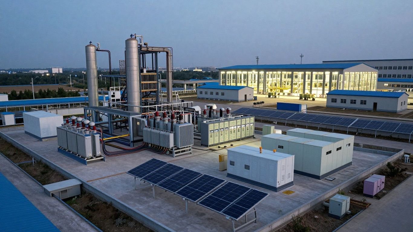
Distributed energy resources may include engines, turbines, fuel cells, photovoltaic systems, wind resources, or other dispatchable and variable sources. Select them according to fuel availability, emissions limits, ramp rate, operating hours, heat recovery opportunities, and the plant’s ability to maintain them.
Generation should be evaluated in combinations rather than in isolation. A dispatchable source may support extended islanding, while renewable generation can reduce fuel use and storage can manage short-duration changes. The final mix must still satisfy fault, grounding, synchronization, and black-start requirements.
Battery energy storage systems and power conversion equipment
A battery energy storage system is sized by both power and energy. Power determines how quickly it can respond and how much load it can support at once; energy determines how long it can sustain that duty. Power conversion equipment also determines whether the system can follow the grid, form voltage and frequency during islanding, provide reactive power, and coordinate with other sources.
Evaluate usable capacity at the expected temperature, state-of-charge limits, degradation, auxiliary consumption, and fire-protection arrangement. The enclosure, ventilation, detection, suppression, and emergency response plan belong in the design package, not in a later facilities discussion.
Switchgear, transformers and power distribution equipment
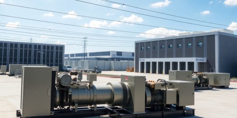
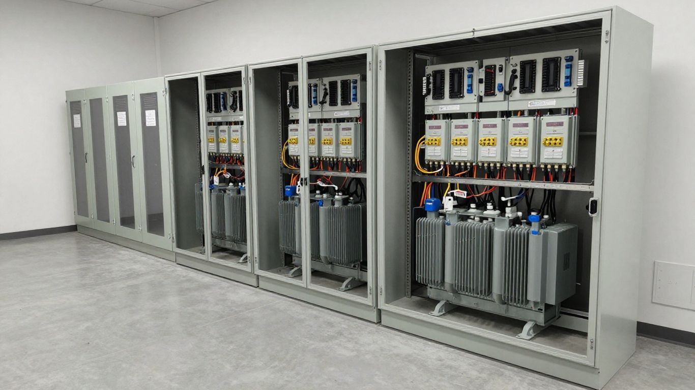
Switchgear must interrupt available fault current, withstand the duty imposed by alternate sources, and support safe isolation. Transformers should be checked for continuous loading, harmonics, inrush, impedance, cooling, and future capacity. Cable and bus selections must account for temperature, installation method, voltage drop, and short-circuit withstand.
The physical arrangement matters too. Keep high-energy equipment accessible for maintenance, separate incompatible hazards, and provide clear paths for incoming conductors and control wiring. A sound layout reduces both commissioning risk and the temptation to bypass safety procedures later.
Protection, metering and grid-interconnection hardware
Protection and metering make the microgrid observable and controllable. The design may require relays, instrument transformers, revenue meters, synchronism check devices, transfer equipment, generator breakers, and communications-enabled intelligent electronic devices. Each device should have a defined purpose in grid-connected and islanded modes.
Metering should capture source output, feeder demand, power factor, voltage, frequency, and energy direction at the intervals needed for operations and settlement. Protection hardware should be selected only after fault studies and coordination reviews establish the required ranges and settings.
Analyze and size industrial loads
Load analysis is where a conceptual microgrid becomes an engineered system. Industrial demand is shaped by shifts, batches, weather, maintenance, production scheduling, and process dependencies. Nameplate totals alone usually overstate some needs and hide short, severe transients elsewhere.
Create load profiles from measured and estimated data
Begin with interval data from utility meters, plant meters, motor control centers, drives, and process historians. Where measurements are unavailable, document the estimate, its confidence, and the conditions it represents. Separate real power, reactive power, apparent power, energy, and operating duration.
Use several profiles rather than one average day. Include startup, normal production, reduced production, maintenance, seasonal extremes, and the planned islanding period. This is also where a Microgrid Design Toolkit can provide background on comparing alternatives against cost, performance, and reliability objectives.
Classify motor, process, thermal and electronic loads
Different load classes behave differently during disturbances. Motors draw starting current and may stall; thermal systems can sometimes be delayed; electronic loads may be sensitive to waveform distortion; and process equipment may have strict sequencing requirements. Capture these behaviors in the load schedule and dynamic model.
For each significant load, record normal demand, peak demand, minimum stable demand, starting method, restart priority, ride-through capability, and dependency on other equipment. This produces a more useful design basis than a single connected-load number.
Account for starting current, inrush and nonlinear loads
Motor starts, transformer energization, large rectifiers, variable-frequency drives, welders, and uninterruptible power supplies can all challenge an islanded system. Evaluate voltage sag, frequency deviation, harmonic current, neutral loading, and the interaction between converters and rotating machines.
Mitigation may include staged starts, soft starters, drive controls, pre-charge sequences, larger or grid-forming converters, harmonic filters, and temporary load shedding. These measures should be tested in the actual sequence in which operators expect to use them.
Match generation and storage capacity to operating scenarios
Capacity should be checked against each meaningful scenario: utility-connected operation, sudden islanding, extended islanding, generator outage, low renewable output, battery at its minimum state of charge, and black start. The largest steady load is not always the hardest case; a smaller load with a severe transient may govern converter or generator selection.
A scenario matrix makes tradeoffs easier to see. It should show available source power, storage energy, reserve margin, shed load, expected duration, and the recovery action. Size for the required service, then confirm that the equipment can operate safely at partial load and during transitions.
| Scenario | Main question | Capacity evidence |
|---|---|---|
| Normal grid-connected | What does the plant draw over time? | Measured interval profile |
| Unplanned islanding | What must remain online immediately? | Transient and feeder study |
| Extended islanding | How long can priority loads run? | Fuel and usable battery energy |
| Source outage | Can another source carry the process? | N-1 operating case |
The matrix should be reviewed with operations, not only with the electrical design team. Its value comes from connecting calculated capacity to decisions people will make during a real event.
Design microgrid controls and energy management
Controls determine whether the equipment behaves like one coordinated system. The design must distinguish fast electrical functions from slower supervisory decisions and from operator commands. Clear ownership of each control action prevents conflicting setpoints and ambiguous failure behavior.
Define primary, secondary and supervisory control layers
Primary controls act quickly to stabilize voltage, frequency, current, or converter behavior. Secondary controls restore operating values and coordinate power sharing, while supervisory controls manage dispatch, feeder states, schedules, alarms, and economic objectives. The layers should have defined priorities and fallback behavior.
Document what remains functional if communications are lost. A microgrid should not depend on a remote server for every protective or stabilizing action. Local controls need safe defaults, while supervisory systems can optimize operation when the underlying electrical conditions permit it.
Coordinate voltage, frequency and power-sharing controls
Grid-forming and grid-following resources behave differently during islanded operation. Establish which source sets voltage and frequency, how other resources synchronize, and how real and reactive power are shared. Droop settings, ramp limits, deadbands, and reserve policies should be coordinated across generators and converters.
The MATLAB and Simscape microgrid workflow provides useful background for scenario-driven modeling of architectures, distributed resources, storage, and control logic. Any model used for a plant project still needs site-specific parameters and validation against installed equipment.
Use energy management systems for dispatch optimization
An energy management system can schedule sources and storage around production demand, fuel constraints, tariffs, emissions limits, and reserve requirements. Its optimization should never compromise protection or the minimum power needed for safe operation. Operators also need visibility into why a dispatch decision was made.
Set clear priorities for economic dispatch, peak management, renewable utilization, battery state of charge, and islanding reserve. Include manual override, alarm handling, data quality checks, and recovery from stale measurements. Optimization is useful only when the underlying meters and controls are trustworthy.
Plan islanding, black start and resynchronization sequences
Write the sequence as an executable operating narrative. Define how the PCC opens, which source establishes the island, which feeders remain energized, how loads are added, and how the system responds to a failed start. Black start may require a battery or other auxiliary source to energize controls, transformers, and initial auxiliaries before larger resources can run.
Resynchronization requires matching voltage, frequency, phase angle, and phase sequence before closing the interconnection. The procedure should include permissives, abort conditions, operator indications, and a controlled return to normal dispatch. This black-start planning guide is a useful reference for thinking through restoration stages.
Engineer protection, power quality and cybersecurity
Protection, power quality, and cybersecurity are closely connected in a modern microgrid. New sources change fault-current magnitude and direction, while power converters add communications and software dependencies. Treat these disciplines as part of the electrical design rather than as separate late-stage reviews.
Coordinate protection in grid-connected and islanded modes
Protection settings that work with a strong utility source may not work when the plant is supplied by an inverter or a smaller generator. Perform short-circuit, load-flow, grounding, arc-flash, and coordination studies for each operating mode. Check directional elements, transfer trips, breaker timing, fuse interaction, and loss-of-source conditions.
The protection philosophy should explain selectivity, backup clearing, permissive signals, and what happens when communications fail. Settings management is also an operational control: approved revisions, access restrictions, and test records are essential.
Manage harmonics, voltage disturbances and reactive power
Measure the existing waveform before adding converters, drives, filters, or large rectifiers. Evaluate harmonic current, resonance, voltage imbalance, flicker, sags, swells, and power factor under changing loading. A filter selected from a nominal calculation can create a new resonance if the network changes.
Use converter controls, passive or active filtering, voltage regulation, and reactive-power support where appropriate. Confirm performance at the PCC and at sensitive process buses. Power-quality limits should be tied to equipment immunity and production risk, not just to a generic report value.
Protect storage systems, generators and critical equipment
Protection begins with correct equipment ratings and continues through detection, isolation, ventilation, fire response, and emergency procedures. Battery systems require attention to thermal events, damaged modules, enclosure access, and separation from other hazards. Generators need fuel, cooling, exhaust, lubrication, and load-bank testing plans.
Critical equipment also needs protection from incorrect switching and failed controls. Interlocks, permissives, local emergency stops, grounding switches, and clearly labeled isolation points help keep abnormal events from becoming personnel incidents.
Secure communications, automation networks and remote access
Segment operational technology from business networks and restrict communication paths to what each device needs. Use strong identity management, encrypted connections where supported, controlled remote access, backups, patch governance, logging, and tested incident-response procedures. The microgrid cybersecurity guide provides a helpful framework for considering DER attack surfaces, network segmentation, monitoring, and audit trails.
Cybersecurity should be designed around realistic maintenance practices. Vendors, integrators, and plant personnel need defined accounts, approval steps, recovery responsibilities, and procedures for operating safely when a controller or network is unavailable.
Validate, implement and optimize the design
A microgrid design is not finished when the drawings are issued. It is finished when the plant can demonstrate the required operating modes without unacceptable risk to people, equipment, or production. Validation should move from models to factory tests, site tests, and supervised operating experience.
Model system performance across normal and contingency cases
Use steady-state and dynamic models to examine load flow, voltage, frequency, fault current, harmonics, motor starting, islanding, source loss, and restoration. Include realistic controls, delays, transformer saturation where relevant, battery limits, generator ramp rates, and communication failures.
Compare results with the original objectives and identify assumptions that could change the conclusion. Sensitivity cases are especially useful for uncertain production growth, degraded batteries, unavailable generators, and unusual weather or fuel conditions.
Test controls, protection and transition sequences
Factory acceptance tests should verify logic, alarms, communications, metering, and equipment interfaces before shipment. Site acceptance tests should then confirm wiring, settings, breaker operation, interlocks, protection trips, and actual transition behavior. Test plans need pass/fail criteria and safe rollback steps.
Do not test only the ideal sequence. Include failed starts, lost communications, unavailable sources, incorrect permissives, low state of charge, and unexpected feeder demand. A controlled failure often reveals more than a successful demonstration.
Commission the microgrid without disrupting production
Commission in stages, beginning with documentation, point-to-point checks, and isolated equipment tests. Coordinate switching windows with production and keep temporary power arrangements clear to every affected team. Energize sections in a planned order, verify measurements, and record the as-left settings.
Operator training should use the same names, alarms, and sequences shown in the control system. Keep procedures accessible on site, and require a formal management-of-change review for later modifications. For unrelated administrative references, even resources such as the Traffic Secrets Book, Zumblies series, IPTV guide, Cookie Policy, and gutter installation service should remain outside the engineering basis and operating procedure set.
Track performance with reliability, energy and financial KPIs
After commissioning, compare actual performance with the design model. Useful measures include critical-load availability, transition success rate, unserved energy, generator runtime, renewable utilization, battery throughput, peak demand, fuel use, power-quality events, maintenance hours, and operating cost.
Review results with operators and maintenance staff, then adjust schedules, reserves, alarms, and procedures through controlled change. Financial evaluation can include lifecycle cost, avoided demand charges, fuel savings, and resilience value; a microgrid ROI guide can help organize those calculations without replacing site-specific assumptions.
Conclusion
Industrial microgrid design works best as a disciplined chain from process consequences to architecture, equipment, load behavior, controls, protection, commissioning, and measured improvement. When each decision is tested against real operating scenarios, the result is more than backup generation: it is a coordinated electrical system that supports safer, steadier production.
Frequently Asked Questions
What is an industrial microgrid?
An industrial microgrid is a coordinated electrical system containing facility loads and local energy resources that can operate connected to the utility or independently when islanded.
Which loads should an industrial microgrid support first?
Support loads tied to personnel safety, environmental protection, process integrity, essential controls, and the minimum equipment needed for a safe restart. Classify other loads according to production value and outage tolerance.
How is microgrid capacity determined?
Capacity is determined from measured and estimated load profiles, transient behavior, islanding duration, source availability, reserve requirements, and contingency cases. Both power in kilowatts and stored energy in kilowatt-hours may govern the design.
Is battery storage required in an industrial microgrid?
No. Batteries can provide fast response, ride-through, and black-start support, but the appropriate mix may also include generators, renewable resources, controllable loads, or other storage technologies.
What is the point of common coupling?
The point of common coupling is the electrical boundary where the facility microgrid connects with the utility system. It is central to metering, interconnection studies, protection, islanding, and resynchronization.
Why are power-quality studies necessary?
Industrial motors, drives, rectifiers, and converters can create sags, harmonics, imbalance, or reactive-power issues. Studies and measurements help ensure that the microgrid does not introduce disturbances that affect production equipment.
How often should a microgrid be retested?
Retesting should follow the site’s maintenance program, equipment requirements, utility obligations, and any major change to sources, feeders, controls, or protection. Transition sequences and emergency procedures should be exercised often enough to keep operators prepared.